
1. GENERAL INFORMATION
It is a formwork system that is manufactured specifically for the project by installing a formwork for structures such as reinforced concrete silos, chimneys, and clinker and is moved by hydraulic systems. It is essential to work 24/7 during shooting. The formwork should be installed in accordance with the project and shooting should be done. Slipform tools should be placed by considering factors such as reservation gaps, embedded steels, tower crane installation location, wind direction. For this reason, the project should be completely examined and installed.
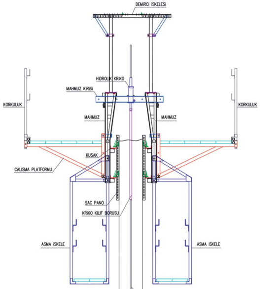
2. DESCRIPTION OF SLIDING MOLD
2.1. PANELS:
Panels 3 mm. thickness, 1200 mm. in height and 1500 mm. wide steel panels. With special fasteners, they are connected to steel belts with 120*120 special angle brackets, they are connected to each other with 4-5 bolts. Internal and external steel is supported with 120*120 special angle iron and steel belts.
2.2. SUPPORT ELEMENTS OF MOLD FORMS
The equipment called sliding mold feet is connected to each other with perforated utils. A complete system is created by connecting the sliding formwork to the equipment called console and tilfir scaffolding placed on it.
2.3. HYDRAULIC JACKS
Hydraulic jacks with a load capacity of 3 tons and an oil pressure of 200 bar are used in silo construction works. All jacks and hoses are connected to the main pump (hydraulic power unit). Jacks at the same time the entire construction of the sliding formwork and platforms 25 mm. they lift it up.
2.4. PLATFORMS
Top of working platform (inside and outside platform)100×100 3000-4000 mm. grilled with wood, 50 mm above. It is paved with thick timber. Walkways are made of 50 mm timber (plank) for suspended scaffolds used for the repair of the concrete surface.
2.5. CLIMBING BARS
Climbing rods 28 mm. in diameter and 3 m. It is made of special metal, which is long. As the die rises, the bars are added together. Each jack is connected to the hydraulic power center by hoses. These jacks hold on to the climbing rod and lift the formwork together, the guide pipes mounted on the jacks leave a gap in the concrete, preventing the climbing rod from buckling, and at the same time providing the possibility of disassembly. The bars are placed when the formwork is set and the jacks are installed and carry the weight of the entire construction. With the concrete pouring application, 1 bar is removed every 10-20 meters, then steel plates are placed under the carrier bars and new bars give their weight to these steel plates. After sliding, the climbing rods are disassembled.
3. OTHER MATERIALS OF EQUIPMENT REQUIRED
3.1. LIGHTING
• Formwork platforms and suspended scaffoldings are illuminated as the work done with sliding formwork is done in a non-stop (24 hours) regime.
• Slipform platforms 2,5 m. Equipped with halogen lamps placed above the safety barrier at a height of
• 100 Wt lamps are placed on suspended scaffolds. • In the sliding form work area, the places needed for night work are illuminated.
• Suitable projectors are placed on the crane arm (boom).
3.2. ESTABLISHING A LADDER FOR VERTICAL ACCESS TO THE SILO
• As the slide form rises, a vertical ladder is required to ascend and descend the silo. This required ladder must be made or purchased from materials with projects and standards.
• The connection method to the shaft is determined for the ladder to be installed, preparations are made in line with this method and the necessary materials are provided before sliding. If embedded steel is to be left on the shaft surface, it is placed at the elevations determined on the surface. Ladder assembly and disassembly are meticulously followed and controlled.
• Ladders are used to reach the silo platform, in accordance with the assembly operating instructions. The rising speed of the stairs depends on the rising speed of the sliding formwork.
3.3. TOWER CRANE
• Concrete, wood and B.A. Lifting the iron materials and leaving them on the working platform is done with the help of tower crane.
• Concrete bucket is connected to tower crane and silo concrete is poured with bucket. A crane with a capacity to lift at least 700-1000 dm3 of concrete is used.
• If the tower cranes will not stop at the height of the silo without connection, connection is made to the silo shaft according to the tower crane feature. For this, the crane to be installed in the silo is determined in advance, the connection is designed if necessary, the connecting rod and embedded steel are made, and it is placed in the concrete when it reaches its level, and it is connected when the connection level comes.
• Minimum 40 m. A crane with a lifting capacity of 2.5~3 tons at the boom end is selected.
4. SLIDING DIE INSTALLATION
• Steel panels (1.20 m high) are placed.
• 120*120 special angle braces are assembled.
• Sliding mold feet are mounted.
• Perforated U mounting follows. • Consoles are placed.
• Consoles follow woodwork.
• The hydraulic jack assembly starts when the platform flooring is completed or in the places where it is completed.
• Climbing rods are mounted. (The distance between the bars is approximately 1m. -1.60m).
• The hydraulic system is installed.
• Railings are installed.
• Electrical installation and lighting are completed.
• The location of the ladder is determined and the installation begins.
• The place where the tower crane will be installed is determined, the place where it will be installed is made suitable and installed.
• Mold size controls are made.
• Optical devices stand and sight boxes are mounted.
• Tools such as welding machine, vibrator, tool box etc. that should be on it are placed.
• Suspended scaffolding and tarpaulins are kept completely and close to the assembly place.
• Final controls are made and it is made ready for sliding.
• Tilfir scaffolds are mounted on the system ready to slide.
5. CONCRETE TO BE USED IN SLIDING MOLD
• Concrete used in sliding formworks should set in 6-8 hours.
• Precautions should be taken with chemical additives to protect from frost/heat in cold and hot weather.
• The maximum value of concrete aggregate is 15–30 mm.
• The slamp level of the concrete should ensure its practical use. This value should be 16 and above slamp.
6. COMMUNICATION DURING BUSINESS
Employees at the construction site, on the sliding formwork and tower crane communicate and direct each other by radio connection.
7. SLIDING MOLD CONCRETE CASTING
• After the sliding formwork installation and assembly control, the concrete is poured into the molds. Pouring With the mobile concrete pump, this level is approximately 4-20 meters high with the pump up to the level where the pump can pour. Concrete is poured with the help of tower crane at elevations that the concrete pump cannot reach.
• Concrete is poured into the mold in layers of 25-30 cm thick, more thicknesses may cause deformations in the mold as well as create problems in the assembly of the B.A. iron.
• The concrete surface must always be liquid and fused with the new layer to be poured.
• Concrete setting control is done by immersing a steel rod into the concrete from the top as far as it can go.
• After the first rise, the condition of the hydraulic jacks is checked.
• The horizontal plane of the formwork is leveled with the help of jack couplings by leveling the climbing rods.
• Verticality is checked with the help of optical devices.
• Since the jack has a lifting length of 25 mm at a time, the sliding formwork rises at 25 mm distances. The verticality of the formwork is checked every 25 cm during elevation (after 3 – 4 m elevation, verticality will be checked every 50 cm). Concrete setting time is adjusted with set retarders. The average daily rise rate in the construction of cement silos is 2.5 – 3 m/24 hours. In clinker construction, the rise is 1.5 – 2 m/24 hours.
• If there are different vertical wall thicknesses in the silo project, the concrete is stopped at this elevation and the formwork is drawn empty. The inside of the mold is cleaned and the shrink mold prepared for this thickness is placed. After all processes are completed, concrete pouring continues.
• Reinforced concrete iron (max. 1 ton) is placed on the formwork platform symmetrically.
• Vertical reinforced concrete iron is placed in accordance with the project and specifications.
• If there is embedded steel, it is placed in accordance with the project elevations.
• If there is any defect on the surface, it is corrected with Sika Mono top 610 – Mono top 620.
• Concrete vibration should be done with 50 – 65 mm vibrators with 12000 rpm.
• Concrete vibration should be done carefully to fuse the new and old concrete together.
8. REPAIR AND PROTECTION OF THE CONCRETE SURFACE
• Damaged surfaces that do not require plastering on the concrete surface are tilfired with the help of a brush or sponge.
• Imperfections on the surface are closed / filled with special cement mortar or concrete.
• It is used (by removing the thinner from the mortar of the curtain concrete (tile mortar should not be used)) in order not to disturb the color uniformity.
• Against high heat and evaporation, the surface is 4 m. It is covered with a tarpaulin, which is in height and attached to the suspended scaffolds. The cover on the shaft should always be damp. It is attached with weights from the edges of the canvas against the wind force.
9. FINISH PHASE OF MOLD WORKS
• When the concrete reaches the final quota, the concrete is cut and the surface is gauged. In order to prevent the mold from sticking, the mold is slowly lifted with the help of jacks. This process can be done until 40-50 cm of concrete remains in the mold.
10. MOLD DISASSEMBLY
• All safety and security techniques are applied during the works. Mold disassembly is done by qualified personnel only.
• Disassembly is done in accordance with all instructions against deterioration and breakage events.
• Climbing rods are removed from the concrete.
• They are cut into pieces with molds, belts and panels, lowered to the ground in blocks that the crane can lift, cleaned and stored.