01
Site Survey
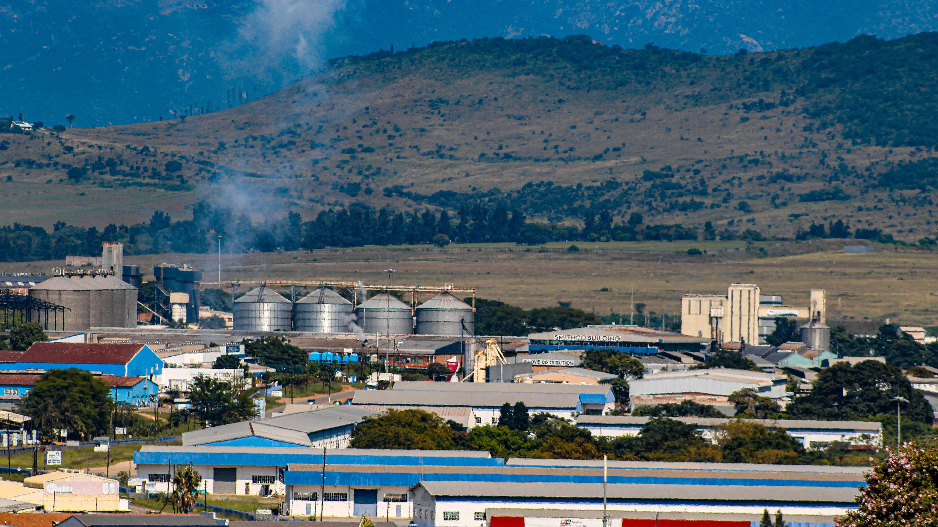
Lime type, dust load and discharge arrangement are assessed during the lime silo site survey.
OUR PROCESS
Lime type, dust load and discharge arrangement are assessed during the lime silo site survey.
The slipform programme and discharge details for the lime silo are set out in the quotation.
Storage loads, diameter and discharge are calculated specifically for the lime silo shell.
Feed, aeration and stair access are integrated into the lime silo design.
Formwork and OHS measures are planned on site to suit production.
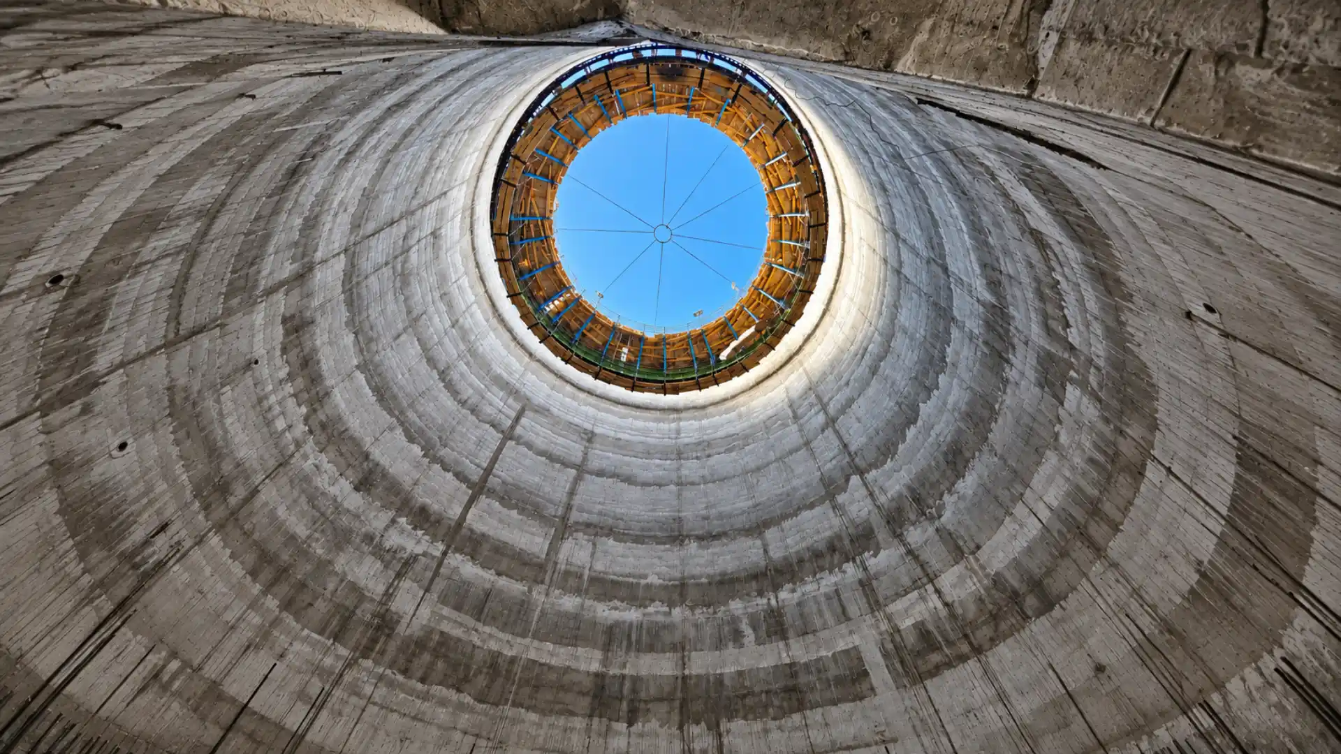
The lime silo rises by slipform, leaving a monolithic shell.
The lime silo is handed over to operations with an elevation and verticality report.
APPLICATION
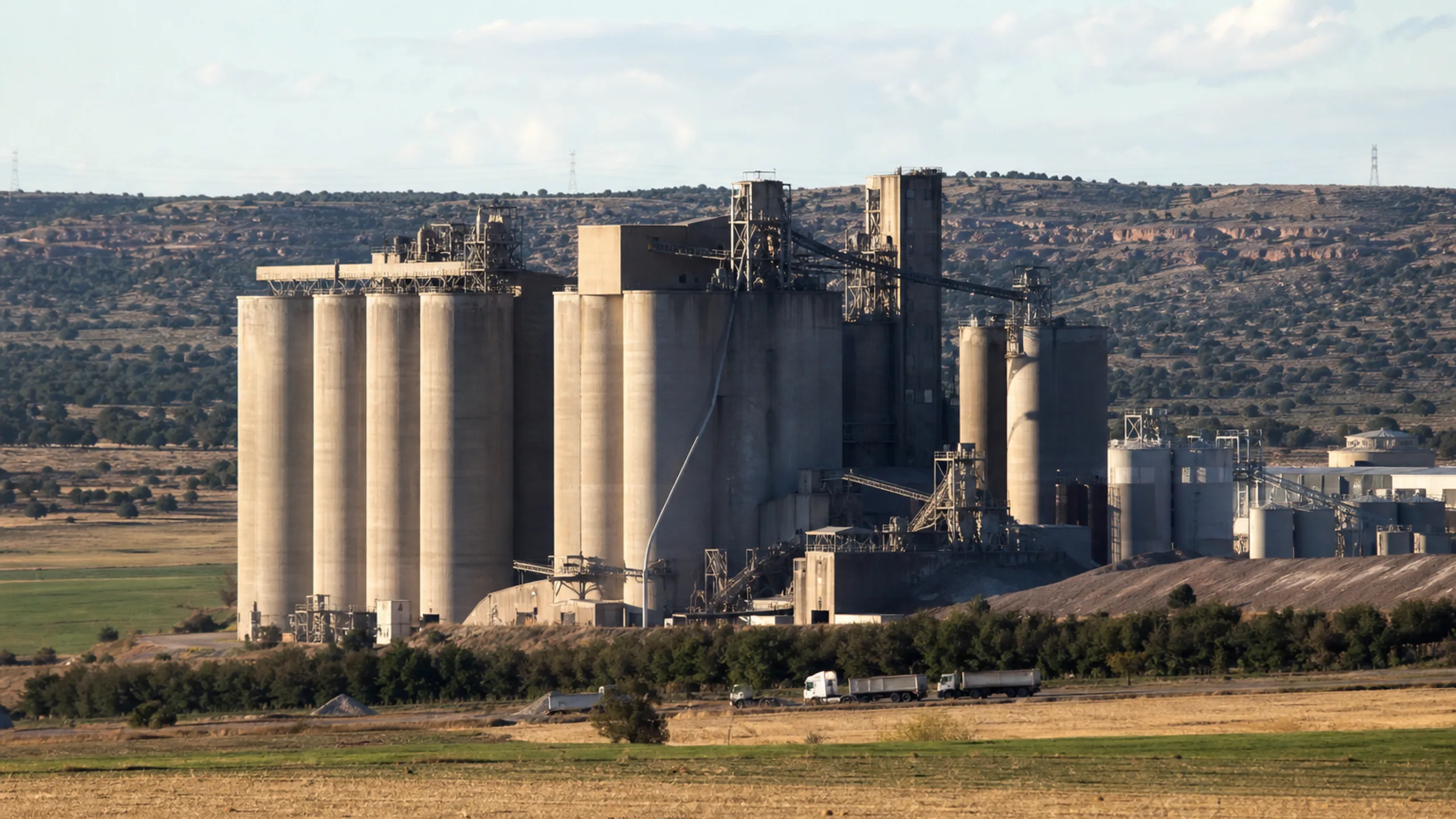
Whether the product is hydrated lime or quicklime changes the cross-section and lining.

Slipform, hopper and dust-tight design are resolved in the same plan.
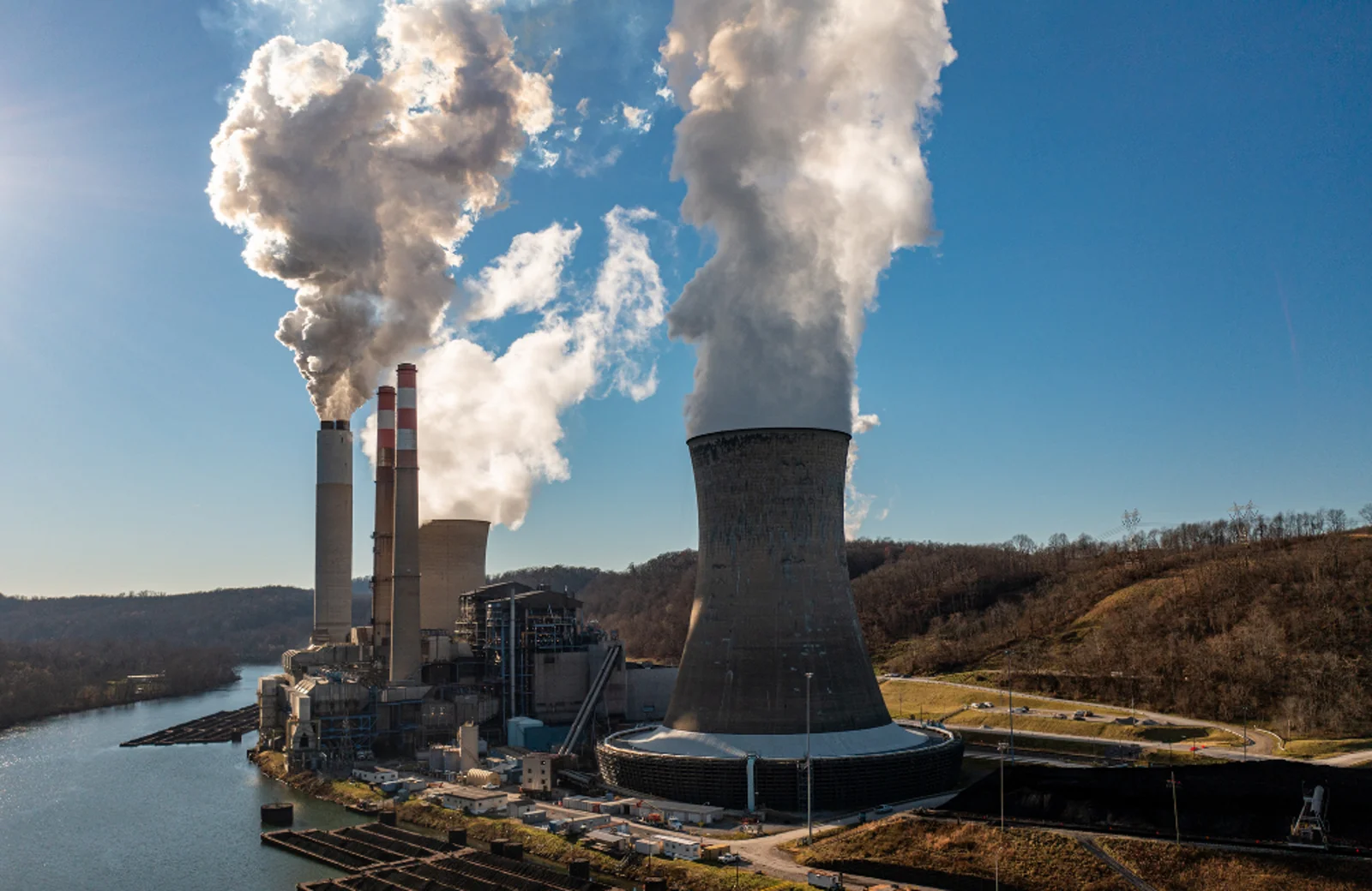
OHS for a dusty site runs in step with concreting. A report is provided at handover.
ABOUT THE SERVICE
A lime silo is one of the specialised silo structures used in industrial plants to store hydrated lime, ground limestone or other lime-based materials used on site. Because lime is used in a range of processes across the cement, iron and steel, energy, chemical, water treatment and mining sectors, silo capacity and equipment layout are determined by the plant's consumption.
As lime and other fine mineral materials can generate dust, silo design must address not only the reinforced-concrete structural system but also filter systems, filling lines, discharge equipment and maintenance access. A flow geometry beneath the silo that suits the stored material helps ensure a steady transfer of material to the process line.
The slipform method can be used for tall reinforced-concrete lime silos. Particularly on projects where the silo walls continue with a similar cross-section over a considerable height, the system allows reinforced-concrete construction to progress within a continuous work programme. Reinforcement and concreting work continue in a coordinated way as the formwork rises.
Before slipforming begins, Rayf Teknik checks that the reinforced-concrete and mechanical designs are fully coordinated. The connection points required for lime filling lines, silo-top filters, maintenance platforms and discharge systems are incorporated into the construction drawings.
During slipform operations, the setting behaviour of the concrete must be monitored continuously. If the formwork rises too quickly, the concrete surface may deform; if it advances more slowly than necessary, the efficiency of the production programme suffers. The concrete mix, ambient conditions and rate of rise are therefore assessed together.
Maintaining verticality is also important in a lime silo. As the silo grows taller, the effect of small deviations at the starting level can be magnified, so survey checks are carried out regularly. Keeping movements at the hydraulic lifting points balanced helps the formwork system advance in the required geometry.
The silo foundation, lower hopper zone, steel superstructure and process equipment connections that fall outside the slipform scope are also part of the project. The work sequence must therefore be planned so that it does not obstruct the activities of other disciplines on site.
Rayf Teknik's approach to industrial silo structures is based on assessing reinforced-concrete construction, formwork technology and the plant's process requirements within a single work plan. On a lime silo project, the goal is not simply to reach a given height, but to create a reliable, functional silo structure suited to the material to be stored, the equipment connections and the plant's operating capacity.
TECHNICAL SPECIFICATIONS
Lime silo diameter, dust load and discharge arrangement are finalised through the site survey and structural analysis.
TECHNICAL ADVANTAGES
In a lime silo, dust, abrasion and slipforming are engineered as one.
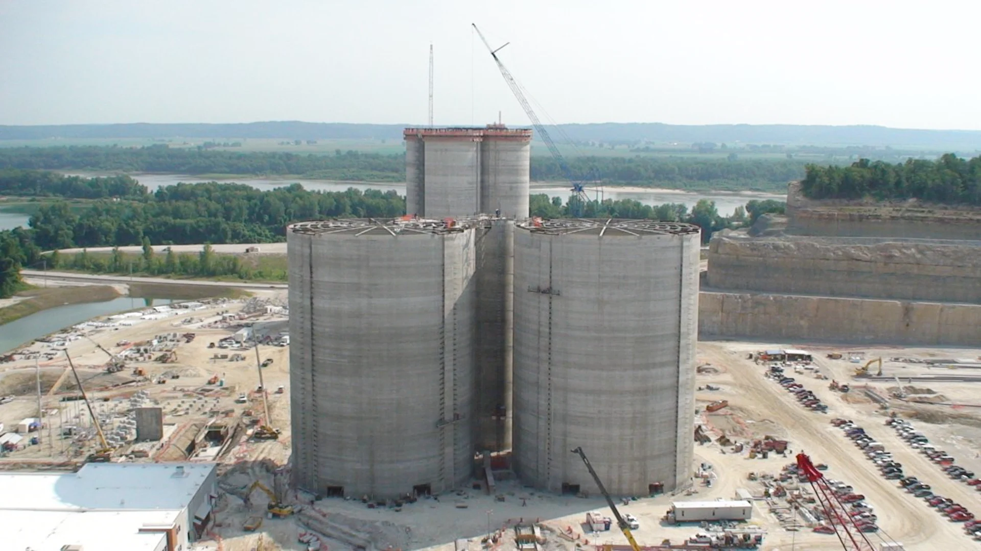
Continuous concrete placement with slipform prevents cold joints and creates a monolithic structure, providing a rigid, watertight and durable load-bearing system for silos and chimneys.
01
Continuous slipforming prevents cold joints and creates a monolithic, rigid structure.
SERVICE GALLERY
OTHER SERVICES
 View Details ↗
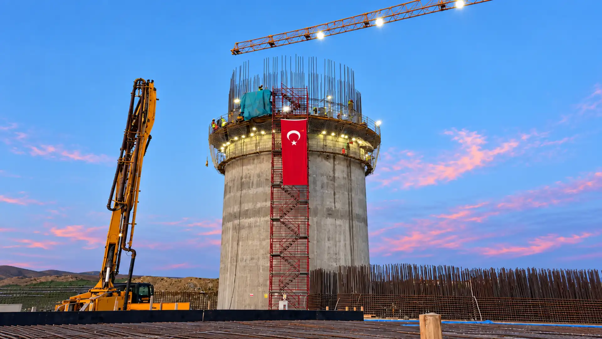
Konya Çimento / Topkapı Şişe Cam
Reinforced-concrete silos are designed to store large volumes of bulk materials. Product loads, the discharge system and process connections define the geometry of the shell.
 View Details ↗
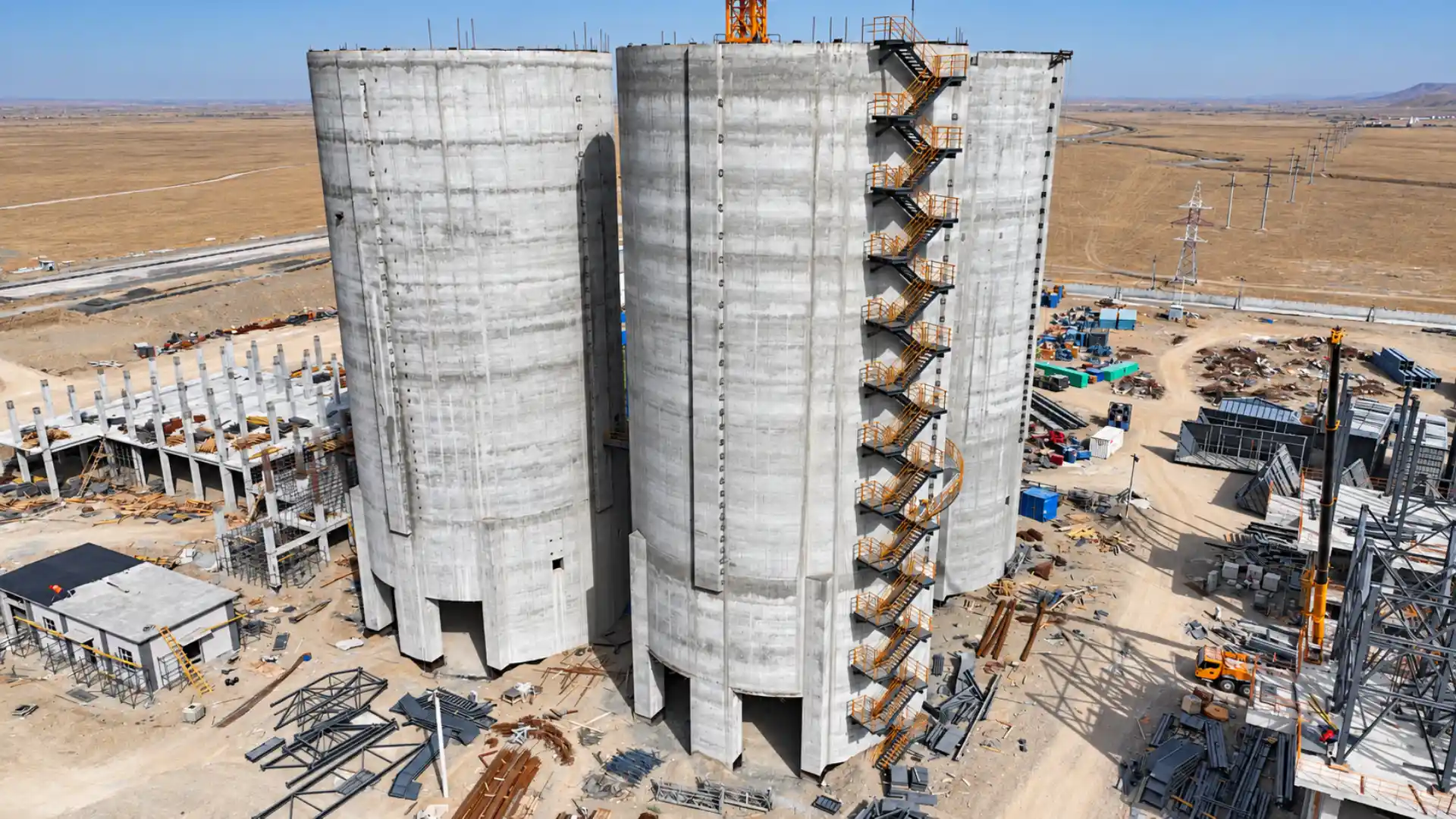
Cement additive and mineral storage line
Additive silos store fly ash, pozzolan and similar fine materials to suit process requirements. The density and flow behaviour of each material shape the silo design.
 View Details ↗
Agricultural and feed storage line
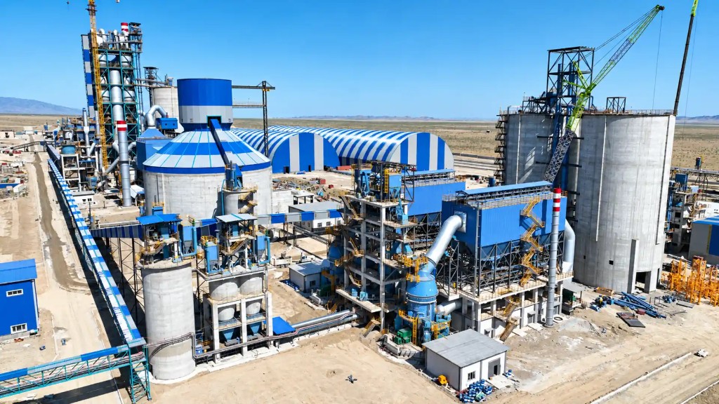
Grain silos keep crops such as wheat, barley and maize in the right conditions from harvest to dispatch. Aeration, filling and discharge are planned together with the shell.
 View Details ↗
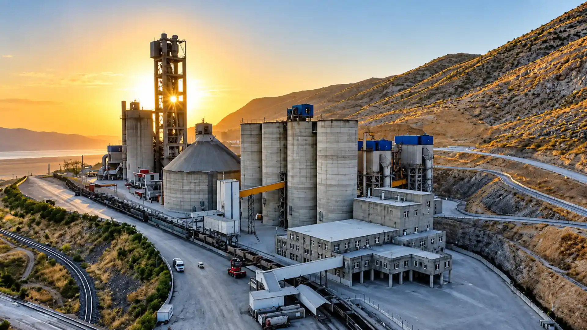
Ilgın / Konya — cement plant
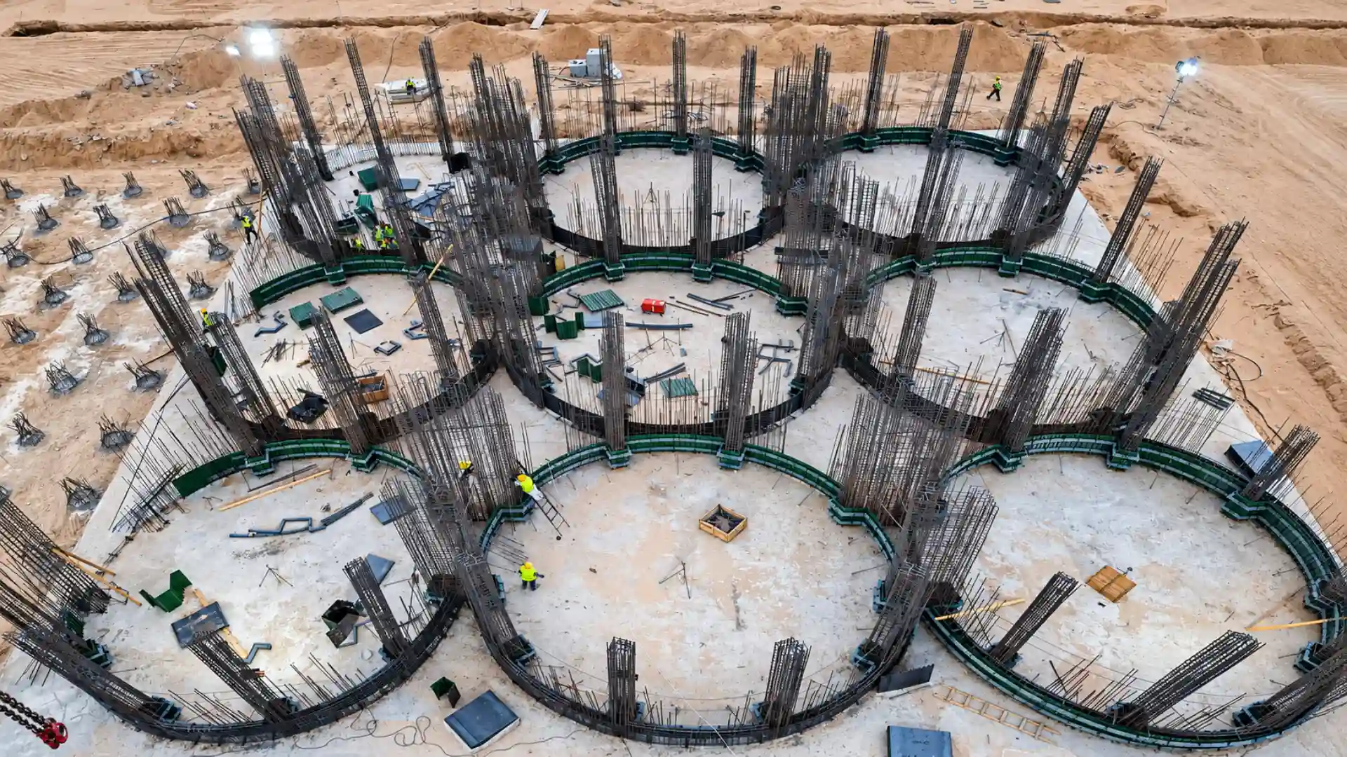
Silo slipforming allows tall reinforced-concrete silos to be built in one continuous pour. Concreting, reinforcement fixing and hydraulic lifting advance together in a single coordinated production cycle.
TECHNICAL SUPPORT
Slipformed lime silo construction for hydrated lime and quicklime: reinforced-concrete shells designed for dust load, abrasion and controlled discharge.
Information & FAQ
Lime silos are used for the industrial storage of hydrated lime or ground limestone. Capacity is determined by the plant's consumption.
Rayf Teknik provides engineering, manufacturing and on-site installation services for slipform systems, reinforced concrete silos, industrial chimneys, structural steel and custom formwork systems.
Our work includes raw meal, cement, clinker, grain and lime silos; bridge and viaduct piers; wastewater treatment structures; minarets and domes; overhead and gantry cranes; and project-specific industrial applications.
We select the system, equipment and execution method according to each project's geometry, programme and site conditions. You can review completed work on our Projects page.
Slipform is a continuously moving formwork method used for tall reinforced-concrete structures such as silos, industrial chimneys, towers, and bridge or viaduct piers.
Hydraulic lifting equipment raises the formwork at a controlled rate while reinforcement work and concrete placement continue according to the construction programme. Continuous placement significantly reduces the risk of cold joints and creates a monolithic concrete structure.
Slipform is not limited to circular structures. Project-specific engineering allows it to be used for square, rectangular, polygonal, prismatic and other custom geometries.
Both systems are used for tall reinforced-concrete structures, but they progress differently.
Slipform rises continuously using hydraulic equipment, allowing concrete placement to proceed without interruption. This provides a major programme advantage for silos, chimneys, towers and similar structures.
Climbing formwork advances in stages. After each concrete lift reaches the required strength, the formwork is moved to the next level and reinstalled. The correct method depends on the structure's geometry, concrete design, programme and site requirements.
Slipform enables tall reinforced-concrete structures to be built quickly and under controlled conditions. Because the formwork rises without being dismantled and rebuilt at every level, it can provide a significant time advantage on large industrial projects.
Continuous concrete placement reduces cold-joint risk and helps create a monolithic structure. Other advantages include high production rates, less repetitive formwork labour, adaptability to different geometries and efficient work at height.
Where technically suitable, equipment can be modified for later projects. We can also provide supervision for clients who purchase a system and carry out the site application with their own team.
Slipform can be used wherever height, repetitive geometry and continuous concrete walls are central to the design. Typical applications include:
Systems can be engineered for cylindrical, square, rectangular, polygonal and other project-specific geometries.