01
Site Survey
Spans, loads and connections are measured during the structural steel site survey.
WORK PROCESS
Spans, loads and connections are measured during the structural steel site survey.
Fabrication, painting and erection are defined in a single steel package.
Sections, connections and anchorages are calculated specifically for the steel structure.
Cutting, welding and surface treatment are completed in the workshop.
Piece marking and OHS measures are tied to the erection sequence.
The steel structure is erected under disciplined crane and bolting procedures.
Weld and bolt records are handed over to the plant operator.
EXECUTION
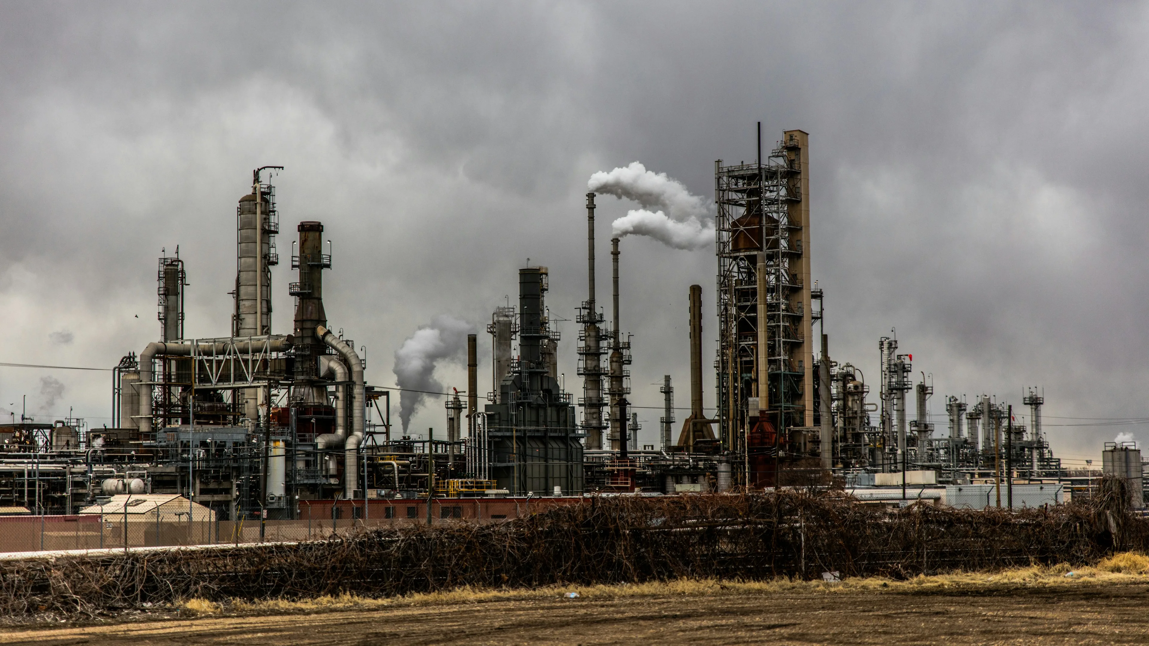
Hangar, platform or chimney steelwork is defined according to loads and access.
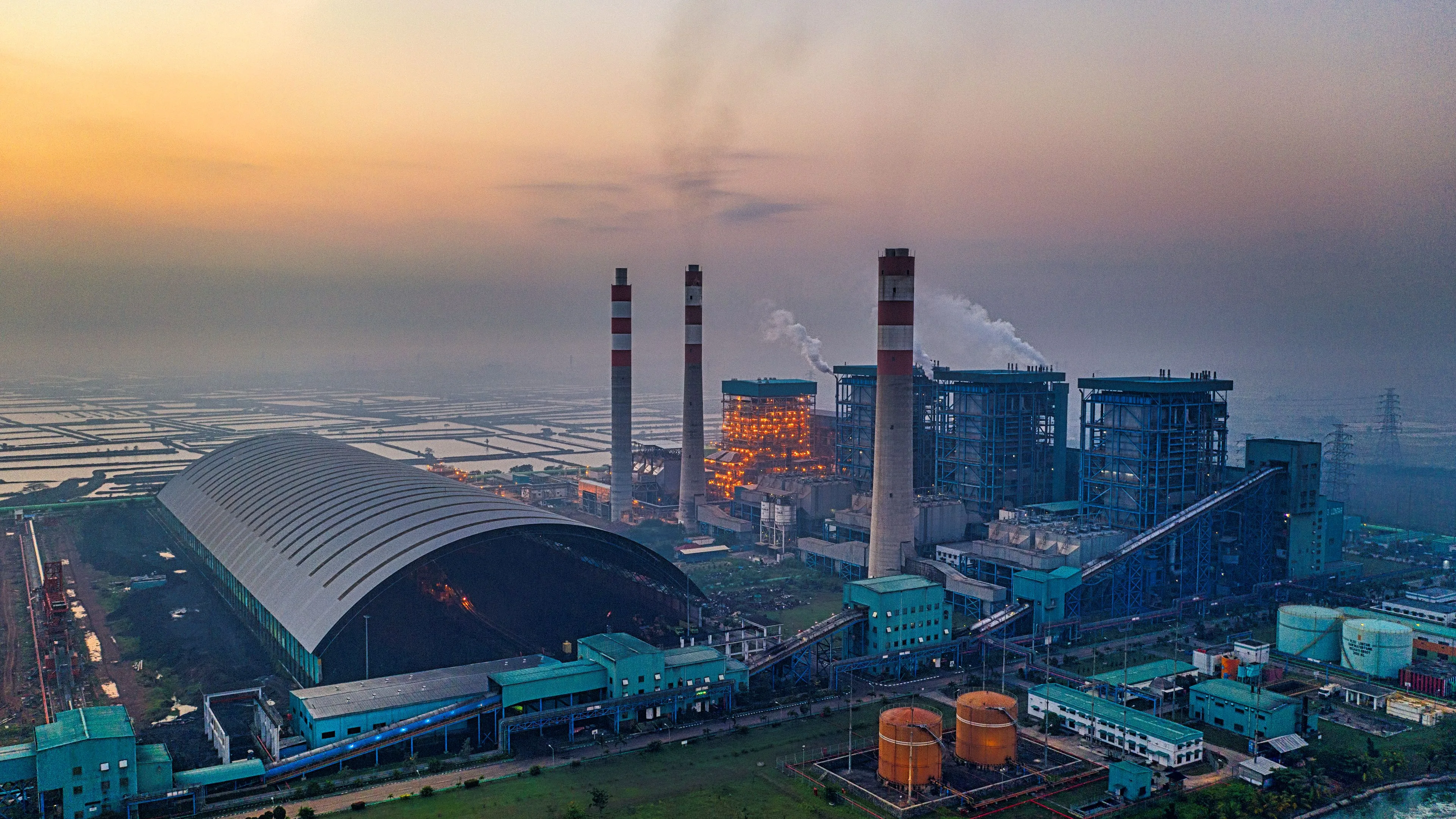
Sections, connections and erection sequence are resolved within a single structural steel design.
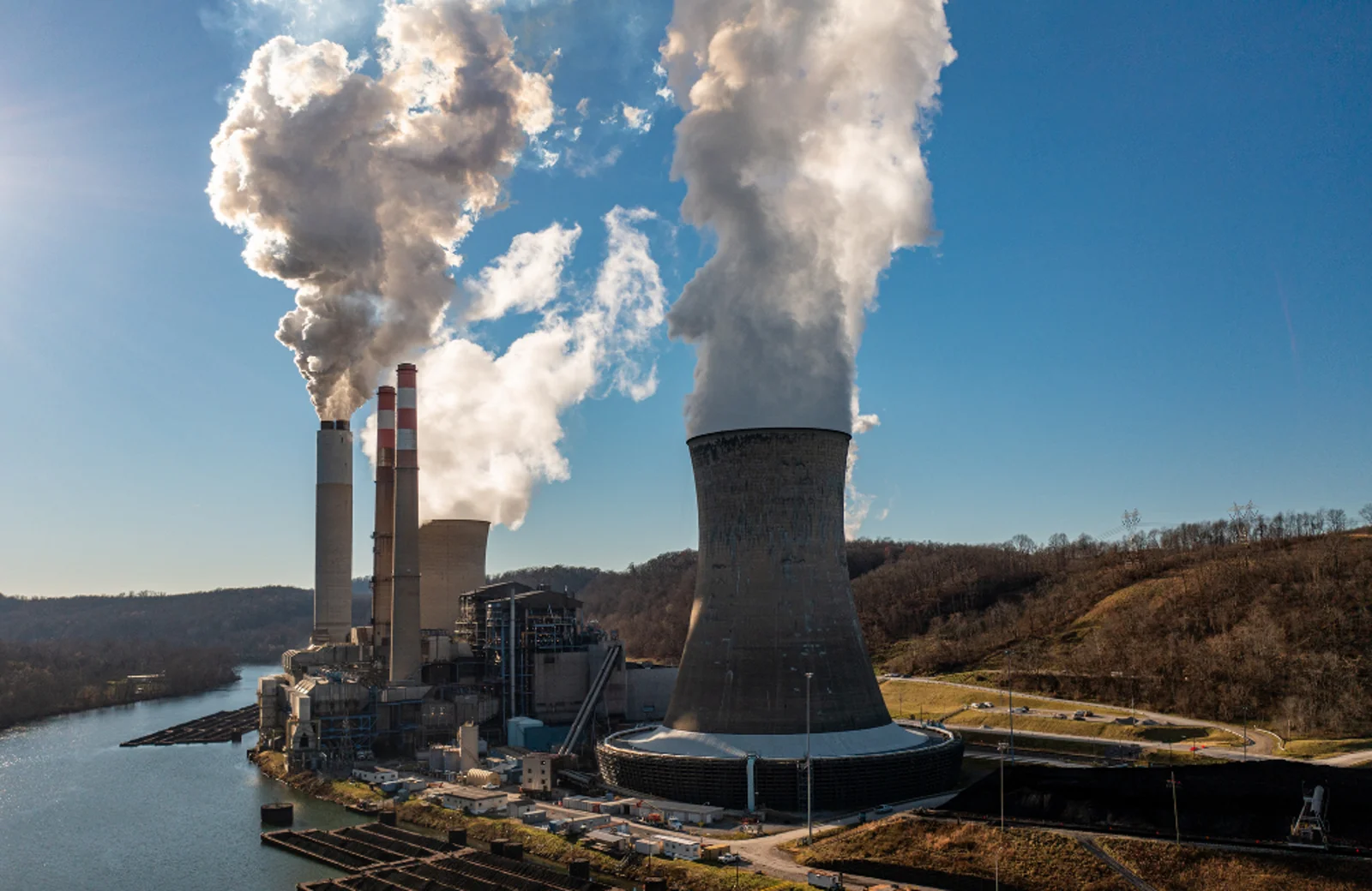
Workshop-fabricated members are erected on site according to their piece marks. Weld and bolt records are provided at handover.
ABOUT THE SERVICE
Structural steel systems are engineering solutions with a wide range of applications, from industrial facilities and production buildings to maintenance platforms and conveyor galleries. The high load-bearing capacity and fabrication flexibility of steel offer a significant advantage on industrial projects, particularly where long spans must be bridged or where new equipment has to be connected to existing reinforced-concrete structures.
At Rayf Teknik, structural steel work is never treated as simply cutting and joining steel sections. The project's structural system, equipment loads, connection points, fabrication tolerances, erection sequence and site access are all assessed before work begins.
In cement plants, power generation facilities and tall reinforced-concrete industrial structures, structural steel often works hand in hand with the concrete structure. Silo roof platforms, chimney stairways, maintenance walkways, equipment supports and galleries can all be connected to reinforced-concrete structures by means of anchorages.
On projects where the silo or chimney shell is built with a slipform system, the structural steel connections need to be coordinated before reinforced-concrete work starts. If embedded plates and anchorage systems are set at the correct levels as the formwork rises, unnecessary breaking out, drilling and adaptation work during subsequent steel erection can be reduced.
Rayf Teknik's ability to deliver both slipform and structural steel work within the same project supports interdisciplinary coordination, particularly on industrial structures. Rather than the concrete team and the steel erection team working to separate design assumptions, the aim is to resolve connection details before execution begins.
During steel fabrication, material selection, cutting, hole preparation, welded connections and surface treatment must all be carried out in line with the project's technical requirements. Preparing components to match the erection sequence before they reach site is another factor that affects working time on tall structures.
On silo and chimney projects built by slipforming, most steel members are erected at high elevations. Assessing crane access, lifting points and erection platforms in advance therefore keeps the work programme running in a more orderly way.
Rayf Teknik's past references also include CEMS platforms and stairways for industrial chimneys, as well as a range of other industrial structural steel fabrications.
The aim of a structural steel project is not merely to produce a load-bearing system. The system must be designed with the personnel who will work on it, the equipment it will carry, the reinforced-concrete structure it will connect to and its long-term maintenance needs all in mind.
By combining structural steel with its slipform and reinforced-concrete experience in a single engineering approach, Rayf Teknik aims to develop fully compatible structural solutions for plants, silos, chimneys and other industrial facilities.
TECHNICAL SPECIFICATIONS
Steel sections, coating system and erection class are selected according to the loads. The rows below show a typical fabrication and erection framework.
TECHNICAL ADVANTAGES
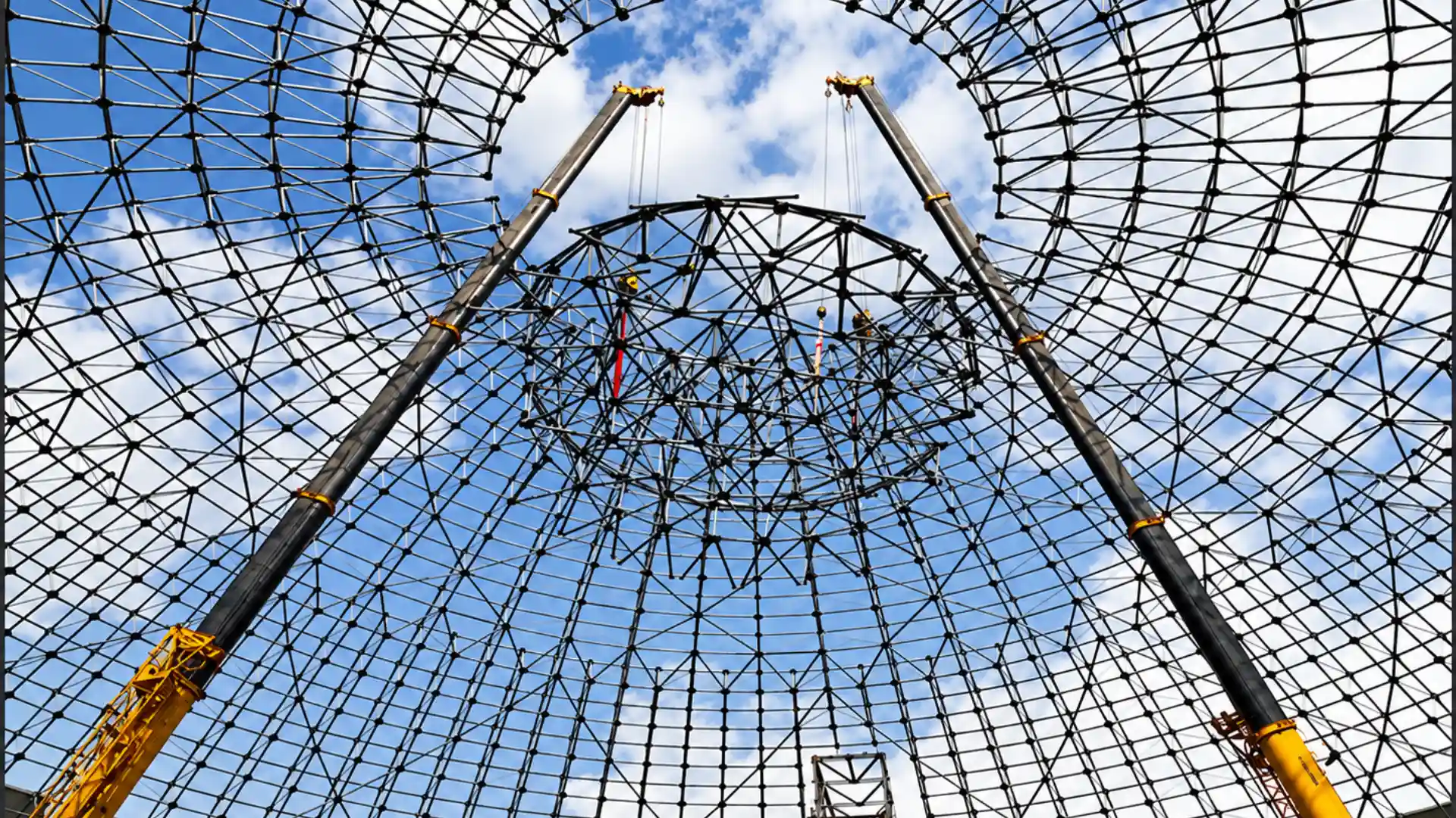
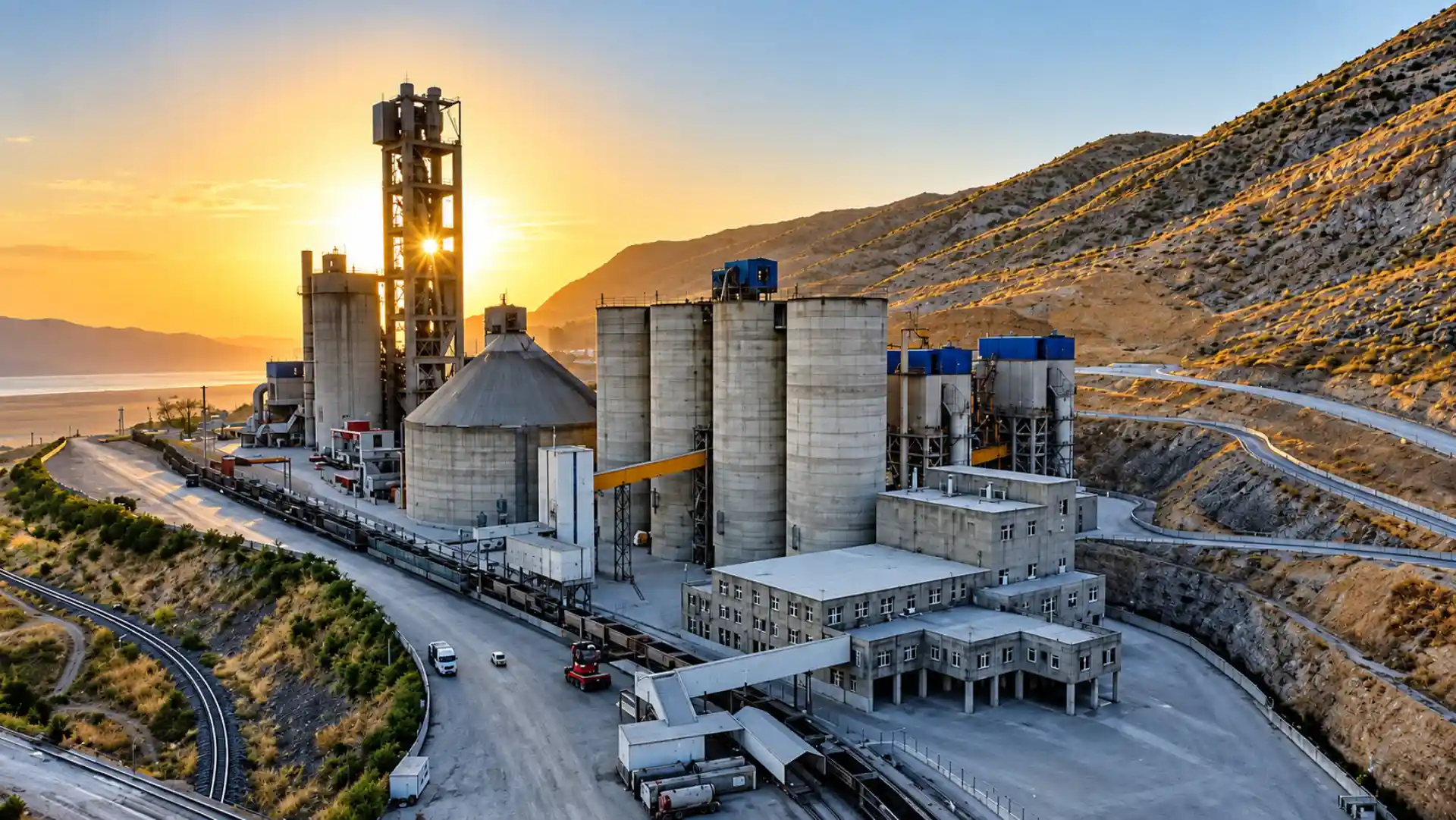
Steel offers fast erection, lightweight long spans and easy maintenance access. The advantages are illustrated with site photographs.
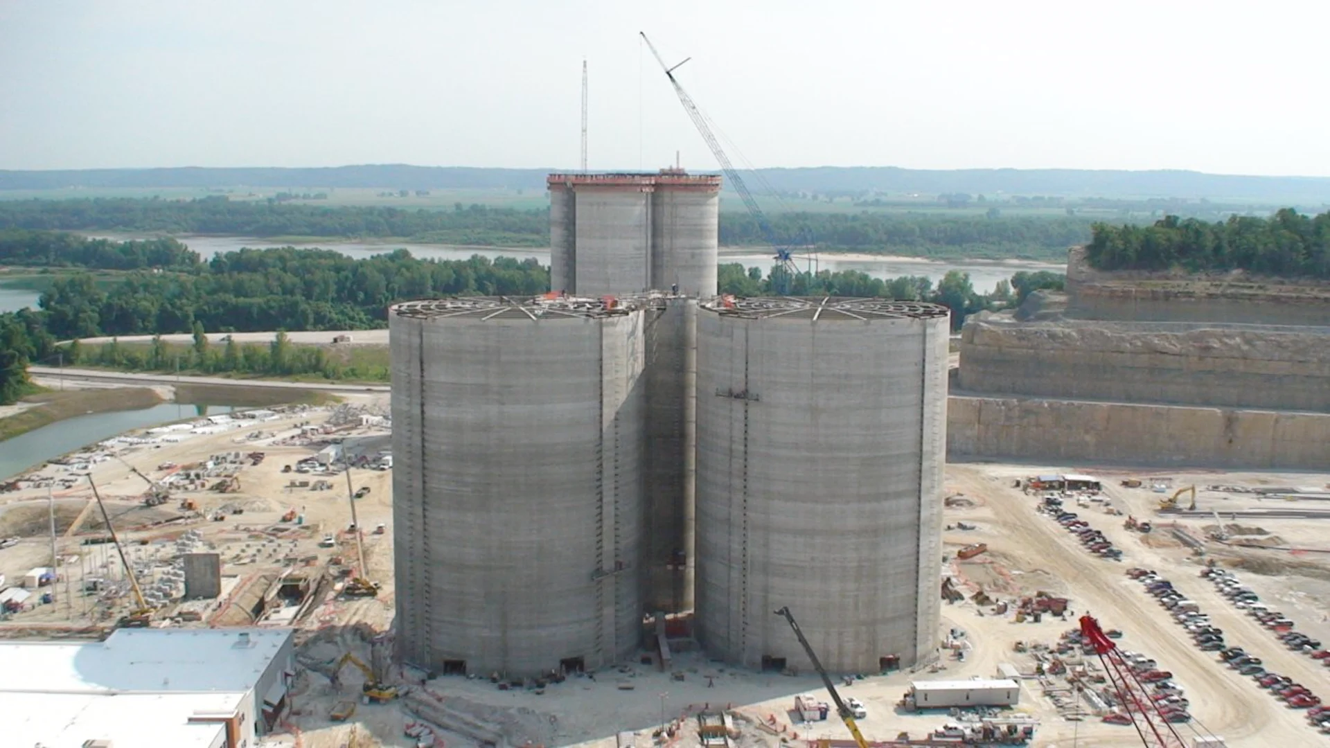
Continuous concrete placement with slipform prevents cold joints and creates a monolithic structure, providing a rigid, watertight and durable load-bearing system for silos and chimneys.
01
Continuous slipforming prevents cold joints and creates a monolithic, rigid structure.
SERVICE GALLERY
OTHER SERVICES
 View Details ↗
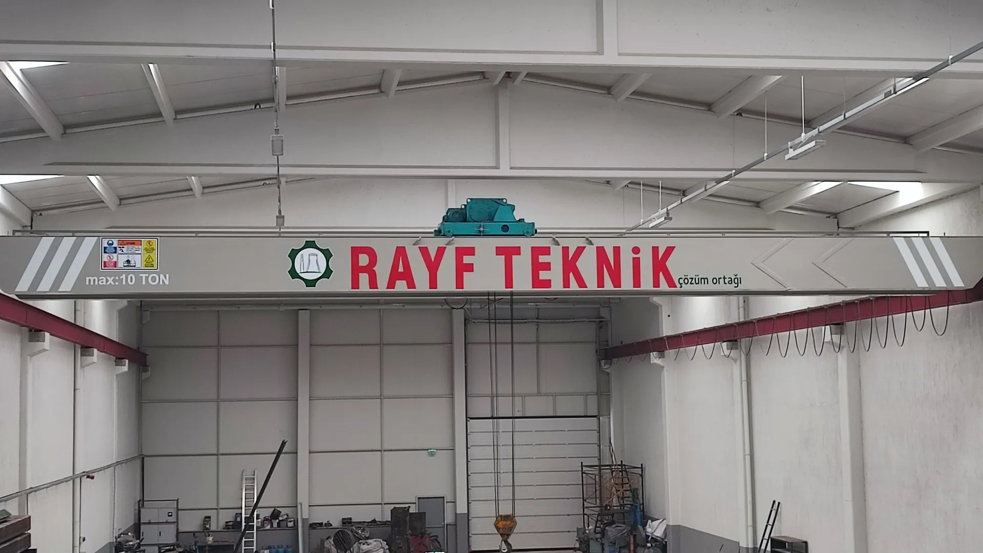
Overhead crane, gantry crane, floor-mounted crane
Gantry and overhead cranes move heavy loads safely and under control across production areas. The crane type is selected according to load, span, lifting height and plant geometry.
 View Details ↗
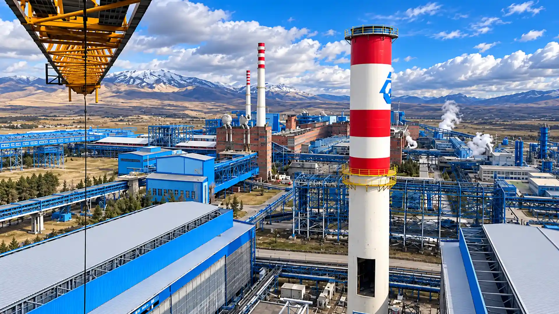
Soma-B Thermal Power Plant
Industrial chimneys are tall structures designed for the controlled discharge of process gases. Wind, seismic action, temperature and maintenance access are all addressed together.
 View Details ↗
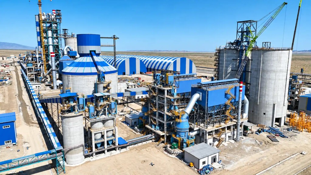
Ilgın / Konya — cement plant
Silo slipforming allows tall reinforced-concrete silos to be built in one continuous pour. Concreting, reinforcement fixing and hydraulic lifting advance together in a single coordinated production cycle.
 View Details ↗
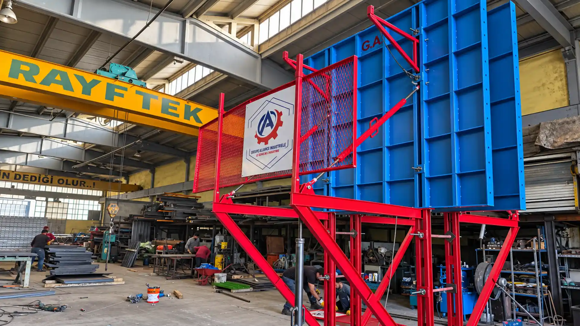
Plain-walled structures of moderate height
Climbing formwork raises tall reinforced-concrete structures in successive concrete lifts. On bridge piers, walls and towers, the formwork is struck and re-erected at the next level.
STEEL SUPPORT
We prepare fabrication and erection quotations for hangars, platforms and chimney steelwork.
Information & FAQ
Fabrication, erection, painting and installation in operating plants.
Rayf Teknik provides engineering, manufacturing and on-site installation services for slipform systems, reinforced concrete silos, industrial chimneys, structural steel and custom formwork systems.
Our work includes raw meal, cement, clinker, grain and lime silos; bridge and viaduct piers; wastewater treatment structures; minarets and domes; overhead and gantry cranes; and project-specific industrial applications.
We select the system, equipment and execution method according to each project's geometry, programme and site conditions. You can review completed work on our Projects page.
Slipform is a continuously moving formwork method used for tall reinforced-concrete structures such as silos, industrial chimneys, towers, and bridge or viaduct piers.
Hydraulic lifting equipment raises the formwork at a controlled rate while reinforcement work and concrete placement continue according to the construction programme. Continuous placement significantly reduces the risk of cold joints and creates a monolithic concrete structure.
Slipform is not limited to circular structures. Project-specific engineering allows it to be used for square, rectangular, polygonal, prismatic and other custom geometries.
Both systems are used for tall reinforced-concrete structures, but they progress differently.
Slipform rises continuously using hydraulic equipment, allowing concrete placement to proceed without interruption. This provides a major programme advantage for silos, chimneys, towers and similar structures.
Climbing formwork advances in stages. After each concrete lift reaches the required strength, the formwork is moved to the next level and reinstalled. The correct method depends on the structure's geometry, concrete design, programme and site requirements.
Slipform enables tall reinforced-concrete structures to be built quickly and under controlled conditions. Because the formwork rises without being dismantled and rebuilt at every level, it can provide a significant time advantage on large industrial projects.
Continuous concrete placement reduces cold-joint risk and helps create a monolithic structure. Other advantages include high production rates, less repetitive formwork labour, adaptability to different geometries and efficient work at height.
Where technically suitable, equipment can be modified for later projects. We can also provide supervision for clients who purchase a system and carry out the site application with their own team.
Slipform can be used wherever height, repetitive geometry and continuous concrete walls are central to the design. Typical applications include:
Systems can be engineered for cylindrical, square, rectangular, polygonal and other project-specific geometries.