01
Cross-Section Survey
Geometry, height, number of reuses and site access are confirmed during the modular steel formwork site survey.
OUR PROCESS
Geometry, height, number of reuses and site access are confirmed during the modular steel formwork site survey.
The module list, joint details and stiffener arrangement are set out in the quotation.
Fresh concrete pressure, plate thickness and the number of connections are assessed.
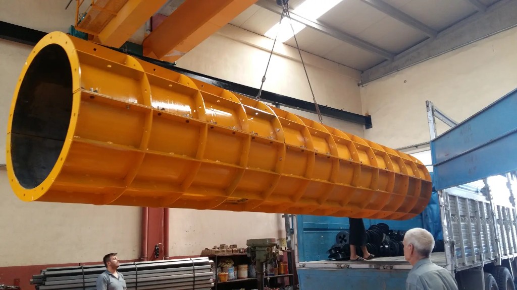
Shells and panels are manufactured in the workshop, painted and prepared for dispatch.
Modules are assembled on site, and the axis, verticality and dimensions are set.
Once the concrete has gained strength, the formwork is opened and moved to the next element or level.
The module list, joint details and operating notes are handed over to the client.
EXECUTION
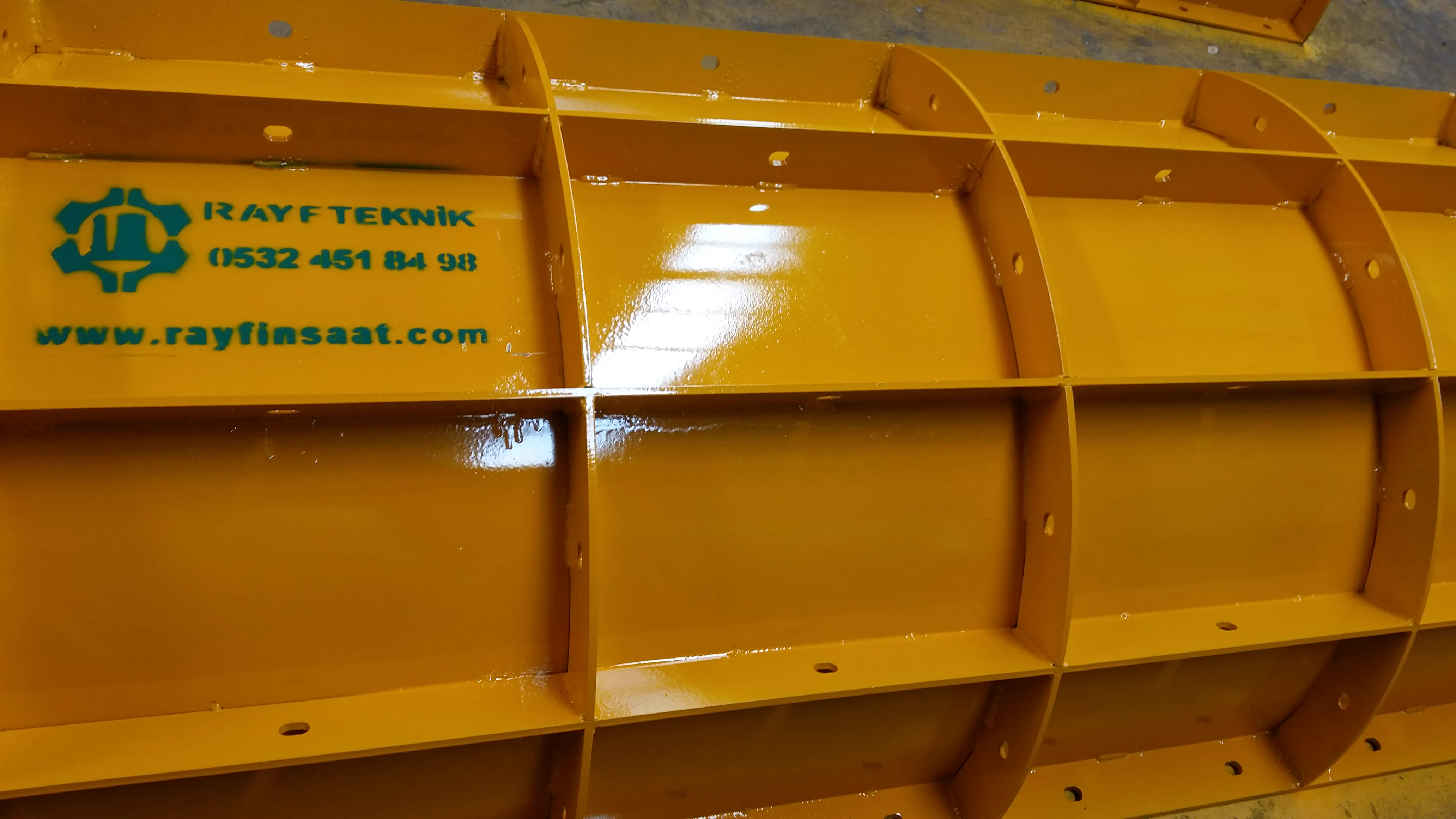
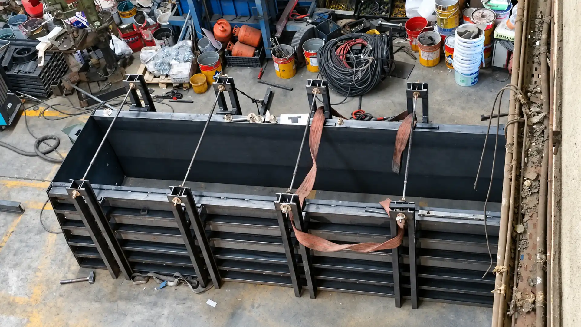
The cross-section may be circular, straight or bespoke. Module sizes are taken from the dimensions of the element to be cast, not from a catalogue.
.webp)
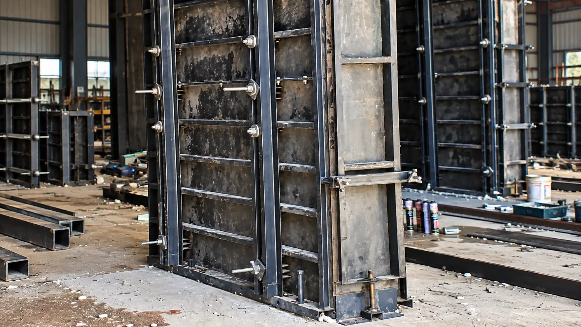
Flanges, tie rods and stiffeners are designed for the fresh concrete pressure. If a joint slips, the geometry is lost.
.webp)
Erection, pouring and striking run as a single cycle. Site supervision can be provided for the first pour.
ABOUT THE SERVICE
Modular steel formwork is a formwork system built by assembling, on site, steel components prepared to suit the cross-section of a reinforced-concrete element. Circular column shells, wall panels and special geometries all follow the same logic: each module is manufactured in the workshop, joined with flanges, bolts or tie rods, struck once the pour is complete and re-erected for the next element.
Components are not tied to a single wall or a single column. Where the dimensions suit, the same shell or panel is moved on to another element. If the dimensions change, only the modules that no longer fit are renewed, while suitable frames, walers and connection components are retained. The system is therefore designed with both the current fabrication and the next job in mind.
On a circular cross-section, two half-shells close at the flanges to form a complete circle. On a straight wall, opposing panels hold the wall thickness by means of tie rods. In both cases, stiffeners carry the fresh concrete pressure. If a joint does not close fully, it leaves a mark on the surface and the geometry is compromised. That is why the tightening sequence is specified on the drawing, and no bolt is ever left out on site.
Door and window openings, starter bars and embedded plates are put in place before the formwork is closed. On tall elements, once the lower lift has gained strength, the module is struck and raised to the next level. This cycle follows the same workshop conventions as our column formwork and wall formwork work. On repetitive cross-sections such as tunnels and culverts, the panel principle stays the same; only the geometry of the module changes.
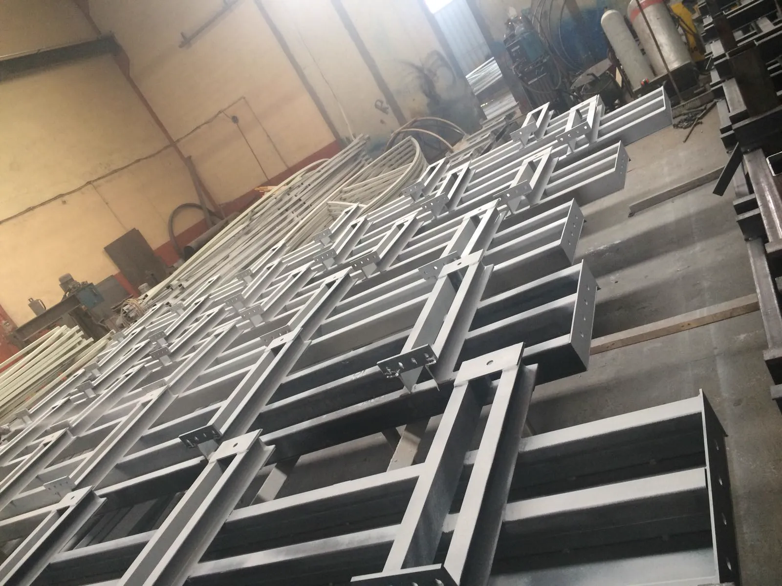
Rayf Teknik treats modular steel formwork not as a single-size catalogue panel, but as a system assembled to suit the cross-section of each project. Stiffened shells and panel frames painted in the workshop are part of this production. Before dispatch, the connection holes and the module sequence are checked. On site, the initial erection is monitored together with the first pour, which confirms that the system has seated correctly.
During erection, the axis, verticality and thickness or diameter are set before any concrete arrives. Vibration must not loosen the joints, and the concrete consistency must not generate more pressure than the stiffener design allows for. The formwork is never struck before the concrete has gained enough strength to hold its own shape. Striking too early damages the surface; striking too late lets the steel bond to the concrete.
Whether the formwork is purchased or deployed on a site contract, site supervision can be provided for the initial erection and the first pour. At handover, the module list, joint arrangement and operating notes are documented. In this way, the formwork is not a one-off sheet-metal job but a production tool that is dismantled and re-erected for other cross-sections.
TECHNICAL SPECIFICATIONS
Modular steel formwork is assembled to suit the cross-section, pour height and concrete pressure. The rows below show a typical application framework.
TECHNICAL ADVANTAGES
Modular steel formwork brings components, joints and reuse together in one solution. The advantages are set out point by point.
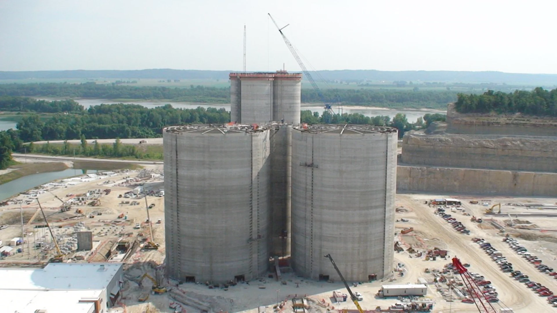
Continuous concrete placement with slipform prevents cold joints and creates a monolithic structure, providing a rigid, watertight and durable load-bearing system for silos and chimneys.
01
Continuous slipforming prevents cold joints and creates a monolithic, rigid structure.
SERVICE GALLERY
OTHER SERVICES
 View Details ↗
Workshop fabrication and site erection
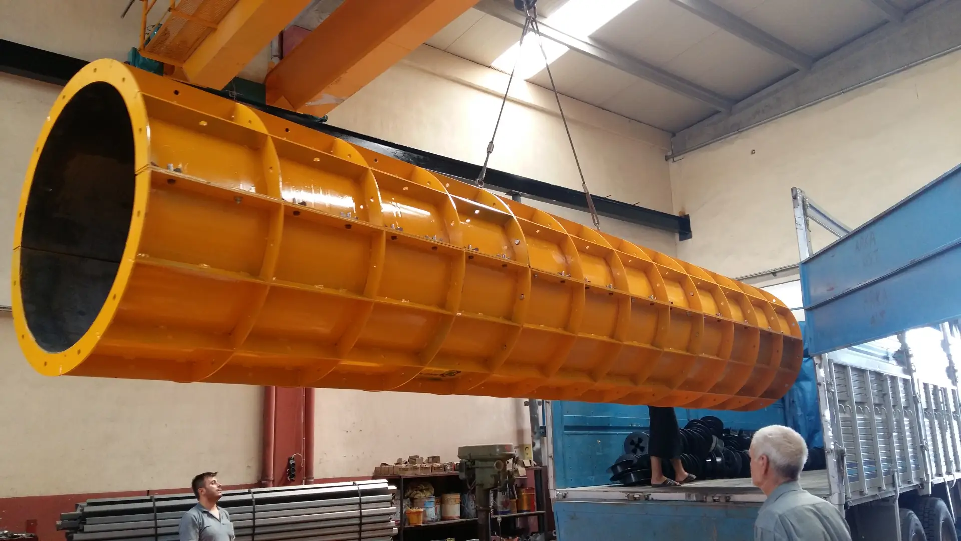
Steel column formwork manufactured to cast reinforced-concrete columns to the design dimensions and true verticality. For circular and special cross-sections, half-shells are joined together on site.
 View Details ↗
Workshop fabrication and site erection
Steel wall formwork manufactured to cast reinforced-concrete shear walls to the correct thickness, verticality and surface finish. Opposing panels are connected with tie rods and stiffeners.
View Details ↗
Metro and tunnel infrastructure projects
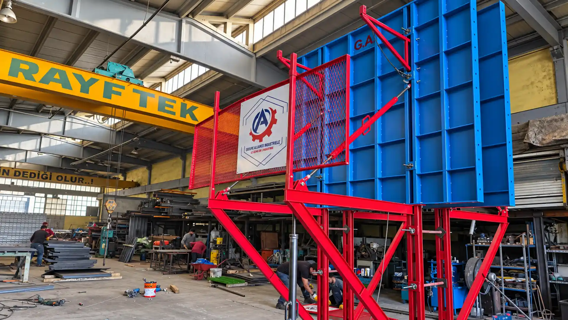
A purpose-built formwork system that forms tunnel cross-sections accurately and repeatably for metro lines, station structures, cut-and-cover tunnels and underground passages.
 View Details ↗
Plain-walled structures of moderate height
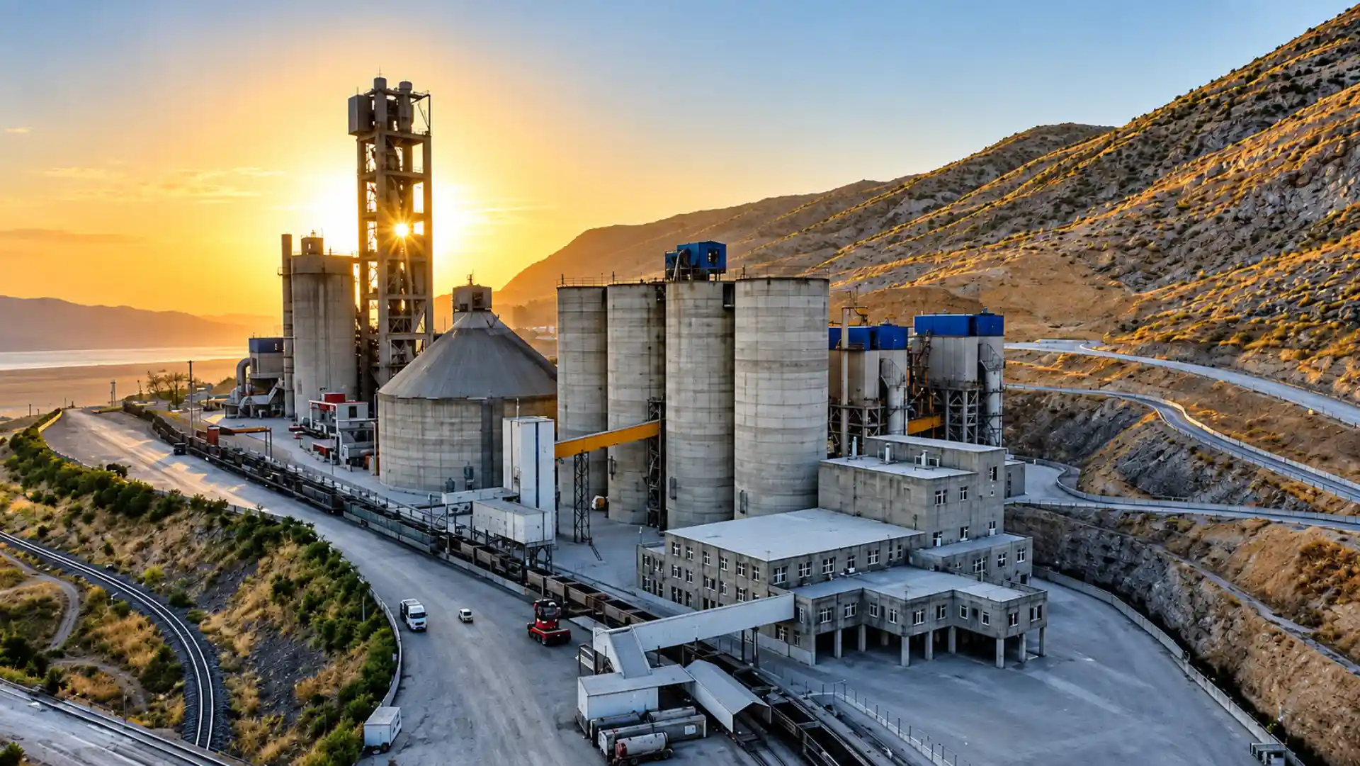
Climbing formwork raises tall reinforced-concrete structures in successive concrete lifts. On bridge piers, walls and towers, the formwork is struck and re-erected at the next level.
TECHNICAL SUPPORT
Our technical team will contact you to arrange a site survey and quotation for your modular steel formwork.
Information & FAQ
Short answers on the scope, timescales and handover of modular steel formwork.
Rayf Teknik provides engineering, manufacturing and on-site installation services for slipform systems, reinforced concrete silos, industrial chimneys, structural steel and custom formwork systems.
Our work includes raw meal, cement, clinker, grain and lime silos; bridge and viaduct piers; wastewater treatment structures; minarets and domes; overhead and gantry cranes; and project-specific industrial applications.
We select the system, equipment and execution method according to each project's geometry, programme and site conditions. You can review completed work on our Projects page.
Slipform is a continuously moving formwork method used for tall reinforced-concrete structures such as silos, industrial chimneys, towers, and bridge or viaduct piers.
Hydraulic lifting equipment raises the formwork at a controlled rate while reinforcement work and concrete placement continue according to the construction programme. Continuous placement significantly reduces the risk of cold joints and creates a monolithic concrete structure.
Slipform is not limited to circular structures. Project-specific engineering allows it to be used for square, rectangular, polygonal, prismatic and other custom geometries.
Both systems are used for tall reinforced-concrete structures, but they progress differently.
Slipform rises continuously using hydraulic equipment, allowing concrete placement to proceed without interruption. This provides a major programme advantage for silos, chimneys, towers and similar structures.
Climbing formwork advances in stages. After each concrete lift reaches the required strength, the formwork is moved to the next level and reinstalled. The correct method depends on the structure's geometry, concrete design, programme and site requirements.
Slipform enables tall reinforced-concrete structures to be built quickly and under controlled conditions. Because the formwork rises without being dismantled and rebuilt at every level, it can provide a significant time advantage on large industrial projects.
Continuous concrete placement reduces cold-joint risk and helps create a monolithic structure. Other advantages include high production rates, less repetitive formwork labour, adaptability to different geometries and efficient work at height.
Where technically suitable, equipment can be modified for later projects. We can also provide supervision for clients who purchase a system and carry out the site application with their own team.
Slipform can be used wherever height, repetitive geometry and continuous concrete walls are central to the design. Typical applications include:
Systems can be engineered for cylindrical, square, rectangular, polygonal and other project-specific geometries.